LimeSDR-QPCIe Control Windows
Note
For DPD demonstration two transceiver channels are implemented in LimeSDR QPCIe board (named with channels A and B). Also, two power amplifiers are required that are connected to the two different transmit paths.
Board Related Controls window
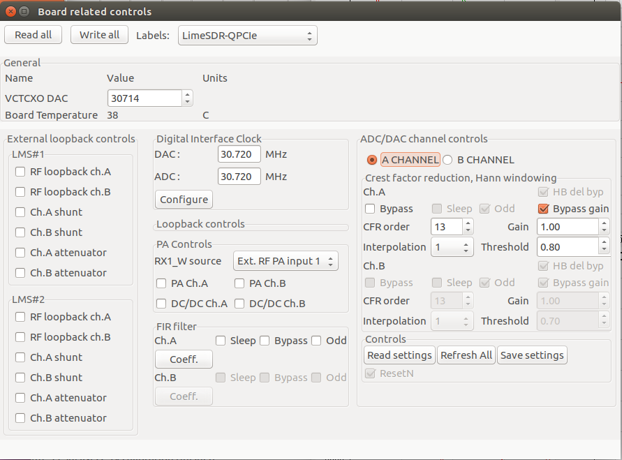
The Crest factor reduction (CFR) controls have been implemented in the Board related controls window, which is the part of LimeSuiteGUI (Figure 15). The window provides:
Selection of the transmitter channels A or B.
Change of PWFIR filter order, in the range from 1 to 40.
Setting the clipping threshold.
To change the coefficients of post-CFR FIR filter.
To turn on/off the LimeNET internal PAs and DCDCs (only if LimeNET internal PAs are used).

Figure 15: The Board related controls’ dialog.
The radio buttons A_CHANNEL and B_CHANNEL select one of the TX paths: A or B (Figure 15).
Two different CFR blocks and accompanying post-CFR FIR filters in the FPGA gateware are dedicated to different transmit paths A and B. Therefore, before any modification of CFR parameters is made, the TX path must be selected using the previously specified radio buttons.
CFR parameters for each of the TX paths include:
Bypass – when is checked, the CFR is bypassed.
Interpolation has possible values 0 and 1 (Figure 15). The value 1 selects the interpolation in front of CFR block. (see Figure 10). In this case the data rate of signals entering the CFR is 61.44 MS/s. Otherwise, when 0 value is chosen, the interpolation is used after CFR and post-CFR FIR blocks. In this case the data rate of signals is 30.72 MS/s.
CFR order is the integer value representing the CFR PWFIR order. When Interpolation=0 the CFR order maximum is 40, otherwise, when control signal interpolation = 1, maximum PWFIR order is 20.
Threshold is the floating point number in the range from 0.0 to 1.0, determining the clipping threshold. The value is normalized to input signal amplitude maximum. The parameter Threshold determines the amount of PAPR reduction. For example, the value of 0.7 reduces the input signal PAPR by 3dB. When value of 1.0 is chosen, the clipping operation is bypassed.
Gain is the digital gain following CFR block. The default value is set to 1.0.
When interpolation or CFR order values are changed in the window, the new Hann windowing coefficients are automatically calculated and are programmed to the dedicated CFR registers located in FPGA gateware.
The low-pass post-CFR FIR filter follows the CFR block
(Figure 10). The options for filter coefficients reading end programming are
provided. When Coeff. button in the Board related controls window is
pressed, the post-CFR FIR filter coefficients are read from FPGA
registers and displayed in the new window. New post-CFR FIR coefficients can be
loaded from .fir file and displayed in the same window. After
pressing OK button, the window is closed and new coefficients are programmed
into the FPGA registers.
Note
For different LTE waveforms
(5MHz, 10MHz, 15MHz and 20MHz) the corresponding files are provided in
folder <LimeSuiteGUI install
folder>/LimeSuite/build/bin/FIRcoefficients.
Since different post-CFR filters exist for different channels, it is required to select the transmitting channel before changing filter coefficients. For this purpose the radio buttons A_CHANNEL/B_CHANNEL are used.
The post-CFR filter length depends on Interpolation. When interpolation is 0, the data rate of post-CFR FIR signals is 30.72 MS/s (see Figure 10). In this case the post-CFR FIR order is 40. Otherwise, when value 1 is chosen, the interpolation is done before the CFR and post-CFR FIR blocks. In this case, the data rate of signals is 61.44 MS/s and filter order maximum is equal to 20.
To save or read gateware configuration the Board related controls window (Figure 15) provides three buttons:
Read settings which reads the
.ini2file, updates the configuration shown in the window and also, automatically programs the FPGA gateware (the CFR blocks and post-CFR FIR filters),Refresh button reads the configuration which is already programmed in the FPGA and updates the configuration in the window,
Save settings is used to read the configuration from FPGA and save it into the
.ini2file.
Beside the CFR and post-CFR FIR configuration, the Board related controls window controls the internal LimeNET Base station PAs and DC/DC convertors. Namely, the LimeNET Base station PAs and DC/DCs can be turned on/off programmatically.
The check buttons DC/DC ChA and ChB (Figure 15) are used to switch on/off the LimeNET BS DC/DC convertors, which provide power supply to PAs (only if LimeNET internal PAs are used). Additionally, the LimeNET BS PAs can be turn on/off using PA ChA and ChB check buttons. Note that when the control is checked, the DCDC or PA is turned on.